
Introduction
There is very little published regarding power systems for professional audio systems and installations, it is often seen as a bit of a black art and in circumstances where we are presented with a poor power system, resolving problems can become a very hit-and-miss affair that appears to many to be the black art it is presented as.
Often we find a staggering lack of common knowledge between the electrical installer and the audio installer which often leads to inappropriate demands from either side. This, however, need not be the case as both industries deal with the very same principles. Simple good practice, engineering and an understanding of the true system requirements can result in a safe, well behaved clean audio system that sits as a good neighbour on the power network.
For the purposes of this document a power supply line shall include the phase, neutral, and protective ground conductors. At no time shall any practice that contravenes electrical safety codes be applied. A perfect audio system power supply is possible within any national code. Where codes require a different method than suggested the code closest to, or exceeding, the system requirements should be followed.
We will not seek here to provide the values or any recommendations as to what system components will be correct for any type of install. There is plenty of literature to help an installer calculate values and loads. Here we will simply deal with the concepts and reasons behind a good electrical supply for audio. Always ensure that you work within any local codes or laws.
–
System requirements
 First and foremost we really must understand what we need from our power system and how the power affects everything that it supplies or comes into contact with.
–
We often hear it quoted that a provided system is far better than we audio folks need because it is an “IT Grade” power system. Well, that really isn’t anywhere near as good as a simple audio system would require. IT equipment generally has a steady state current draw and any variation is most often global and gradual. Further to this, most data signals are in the few volts range and only have a full-on and full-off valid state whilst being in the very high frequency domain. In the bigger picture of things, whilst continuity of supply is paramount for IT purposes and power drop-outs can cripple a system, it does not have any extreme requirements in the current or cleanliness domains.
In comparison an audio system of any consequence will have a pulsating variable power demand of an almost random nature (fully relative to the audio material) caused by power amplifiers.
 Systems can demand hundreds of amperes of current for a mere instant and nothing for a short while after. Large quantities of DC smoothing and reservoir capacitors in most systems can present enormous demands at turn-on. The largest of systems spread across multiple phases and distribution legs can demand a rather uneven delivery of power that is unique to the particular program material requirements at that point in time. Further to the rather brutal power demands we have a very delicate fragile electrical signal that is our audio program, this delicate signal is the primary purpose of our systems and is required to be as pure as possible in order to deliver the best result. Just as an example an analogue line level signal prior to mix processing can in the highest quality systems possess a dynamic range of up to 120db before the digital converters become too noisy. This often leaves us with a valid audio signal down at -100dbV or below, generally in the microvolt region. Microphone signals sometimes fall even further below this. Any introduction, no matter how small, of outside electrical signal upon this microscopic voltage has the potential to ruin the whole purpose of our audio systems.
We, as an industry, are way more sensitive to power line problems than IT equipment, and we are well into the realms of laboratory grade power requirements. We do have a contradiction in what we need and how our equipment behaves, on one hand we require virtual perfection in terms of cleanliness, whilst on the other hand our equipment behaves badly in terms of presenting a severe dynamic load. The only way we stand a chance of achieving anything acceptable is to have an exceptionally good power system that can take all the abuse we give it without delivering any interference.
–
Basic supply properties
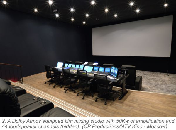
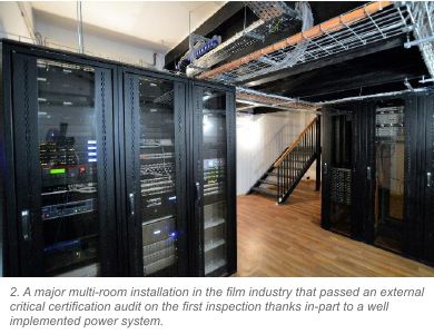
From what we have seen above we would think we are asking the impossible but thankfully what we need really isn’t so difficult to engineer. In all cases and in every aspect our friend is a low impedance source. [Source being at the local point of equipment power line connection, not just the utility company’s transformer]. Fortunately for us the output of a power distributor’s step-down transformer is usually clean and has a very low impedance. Analysis performed over the last three decades by the author and others has shown consistently that if we go far enough back down a 2. A Dolby Atmos equipped film mixing studio with 50Kw of amplification and 44 loudspeaker channels (hidden). (CP Productions/NTV Kino – Moscow) power distribution chain we will eventually find “clean” power well before we get to the transformer. It can however be very difficult in more residential environments to get any assistance going any further back than the power feed to the property, but occasionally it has been found that power companies do find things like poor line connections to be of interest to them if correctly reported.
It is highly recommended that serious audio systems installers should understand to a reasonable level exactly what they need from a power source and often it is very advantageous to be able to measure and analyse the power that is being supplied. A multi-function installation tester can be an invaluable test tool and recent pricing has brought them well within the reach of most installers. If you are professionally installing a critical listening system, or a large scale sound system, it is imperative that you have the means to test and verify the power you are being supplied.
The average electrician is usually only trained and disciplined in supplying power to average appliances, much of what they do on a day to day basis does not apply to high power or critical audio systems. It is imperative that in their day to day work they follow the standard basic rules if only to absolve themselves of any liabilities. It is important that we understand that the usual requirement for cable choice in standard installations is operating temperature and the calculated constant load end of line voltage drop. This is balanced against profit from the job and the smallest acceptable cable section is most often applied to that circuit. There is no consideration by the electrician of the ability of the supply line to conduct interference back to source, pick up interference, or in many cases for the demands of unusual dynamic peak loads. Phase loading calculations are performed based on constant current draw and phase load is balanced to prevent voltage shift where one heavily loaded phase may cause increased load imbalance in the neutral having a negative effect on the supply voltage, not only at the phase in question but also at the other phase terminals.
High frequency interference and distortion artefacts are often never considered when specifying an electrical installation unless they present hazards to the distribution system itself in terms of leakage currents or thermal considerations. Many electronic power supplies used in audio and IT equipment utilise high power high frequency current and this is often radiated around the circuitry. In many cases it is screened out and filtered by simply shorting it to ground (either power line ground return (N) or circuit protective ground (E) through a high pass circuit. The currents, once filtered are not very high and are generally assumed to be easily filtered out, but this assumption is based on a good low impedance return path being available. Where we have many racks of such equipment what is seen as normally insignificant levels of filtered current can easily become a significant current. It doesn’t take many high frequency power supplies to nuisance trip a standard 30ma RCD device, as few as 7 perfectly working units have shown to exceed the RCD current in certain circumstances. In larger systems filtered currents can be very significant. If the power supply is not of adequately low supply impedance we can get these currents failing to be adequately conducted (filtered) out and beginning to remain present in the lines, equipment chassis, or in the supply output. In the case of such units it is critical that a good low impedance power line is supplied if we are to avoid high frequency interference. Many people will have heard this type of interference on consumer computer sound devices that are poorly grounded or ungrounded (Class II).
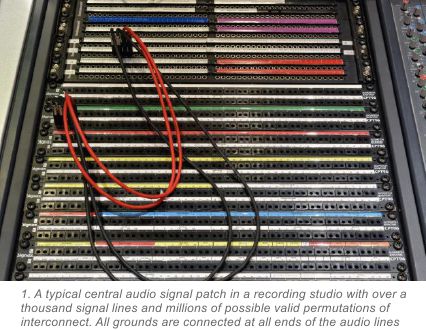
Unlike much other equipment, with audio systems the system protective grounding, or equipotential bonding, is an integral part of the product signal of the system. Normally it is simply a means of protection against electric shock. In order to reject airborne RF and other induced interference, sensitive audio equipment has to be shielded, this is the case with virtually every piece of audio equipment and every single analogue interconnect. Cable screens are simply an extension
of the screening metal equipment enclosures and racks there to provide a protected [shielded] conduit from unit to unit for our delicate audio signal. Most modern professional system equipment uses balanced interconnects, but there are various methods and points within all the different pieces of equipment to reference the power supply 0 Volt rail to the protective chassis ground conductor so there is a physical relationship between protective ground and audio 0V reference in most audio systems. Some equipment has physically isolated [transformer balanced] floating signal inputs, other has electronically connected differential input circuitry, and there is a lot of variation from equipment to equipment depending on purpose or cost. Unfortunately, eventually at some point in most systems we will encounter an unbalanced interconnect which will invariably use the screen of the signal cable, and hence the system electrical protective ground, via the enclosure, as the 0V audio signal reference for the transmission path. Most source devices like computers, MP3 players, CD players or DJ mixers along with most professional musical instruments will be of an unbalanced interconnect nature, and thus be a point where we have a direct audio signal to ground connection. There is therefore a compelling requirement for a clean ground path between devices, and ultimately to the electrical safety ground reference.
The principle requirements for a successful audio system power installation simply relies on a good very low impedance power source, adequate peak current delivery, and a very low impedance reference ground between all items of equipment.
–
Methods to ensure a good supply
The foundation for a successful audio installation is the power source, everything relies on the power. This is something that is simple to specify correctly early on in a project. Depending upon the nature of the project it can be anything from asking for a new radial line to getting the electricity supplier on bigger jobs to fit a new supply to the building if the existing supply is poor or inadequate.
 One thing that is best practice is to make sure we share as few branches as possible from source with other equipment or services. Don’t tag the audio rack onto the kitchen and office power distribution board when we can pull a line back to the main board at the front door and only share the cable from the street. If we share a line with other services we want it to be as big and low impedance as possible so that any distortion or interference caused is minimised and left on the separate line to the offending equipment if it is a function of poorly specified lines or connections. In a larger scale situation where we are a unit in a bigger building we should try to get our feed from the closest distribution board to the incoming cable rather than share lines with others. This may require pulling in new lines and negotiating with the building’s owners, but in the long run it can be far less expensive than trying to remedy problems, caused by other users, with aftermarket bolt-on filter solutions. This job often requires some serious detective work and often the cooperation of more than one level of property management or tenant. If fitting a nightclub in a shopping mall its best that we do not share a local power board with the main HVAC plant – better to ask for, and pay for a new line from the main switch room.
Once we have found a good low impedance source we need to bring it to us, it’s no good finding a low impedance source and turning it into a high impedance source by using thin cables. We need to do the calculations and try and not to increase the source impedance by much. This will often involve over-sizing of cables when compared to the usual regulation recommended cable section. There is no reason not to use larger section cables (as long as they are equal section on all conductors) other than financial reasons or having to increase the size of terminals. Cable section will largely depend on the peak power demand of the combination of all of the highest current devices, and whether the devices have low or high frequency power supplies. Irrespective of current demand we still need to maintain a low impedance source, so we would have a minimum cable size threshold that keeps our system a low impedance supply. In the case of remote equipment rooms this may well result in some abnormal requirements, such as a 63A feed cable to a remote DJ box. There is no hard and fast rule of thumb as there are so many issues that can affect the requirements from noise floor requirements to power consumption demands, but the general case is that we would at least need the next size up in terms of cabling from what an electrician would normally specify. For large studio systems we try and maintain well under a 1 ohm source loop impedance for all audio circuit power outlets (often half of that or less) , and well below a ½ ohm difference between all local end of line values.
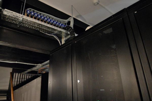
4 Equipment rack fed with 13 x 16A lines each on 6mm cable where high power equipment shares rack space with IT and sensetive audio systems. That’s a lot of copper back to source.
–
Multi-phase Supplies
When we are given a 3 phase supply the supply should be designed for extreme imbalance. In some countries the standard 4 or 5 core 3 phase cable assumes a level of balance and actually has a smaller neutral. This type of cable must be avoided at all points in the system or serious problems may occur. On a perfectly balanced 3 phase supply no current at all will flow through the neutral, so often the neutral conductor can be nothing more than a ground reference or more commonly intended to carry only the imbalance between relatively balanced lines, often this can be as small as half the sectional area of the phase conductors. This level of balance is not the case with audio or entertainment lighting systems and such supply cables can be very dangerous indeed. Depending on where we are working we must make sure we have a supply capable of a total imbalance (one phase only fully loaded while the other two are totally unloaded) Serious imbalances in badly supplied three phase supplies can be extremely dangerous and lead to overvoltage situations on the lightly loaded phases, a large scale distributed audio system is a very unpredictable load. Similarly where systems may operate from generators we must make sure that our source is capable of working with uneven dynamic phase loading and has adequate sensing. In most circumstances we are never going to exceed even a tiny percentage of the utility company’s 3 phase LV transformer capacity unless we have some form of monster sound system and a small supply, so as far as supply transformer load is concerned we will not present such a huge imbalance to the extent of upsetting the source. Definitely no more than the average street of houses usually will.
In cases where older AV equipment is in use with analogue signals there are situations where many video devices will not work correctly if they share supplies from different phases as they often use the power line frequency as their sync reference. The common result is a shadow bar across the screen. This is a very important reason to keep all technical systems on the same phase where possible to avoid having to fit isolation or external sync devices. The requirement is far less with more modern systems as digital signal is independent of power line frequency and often asynchronous. The technical or signal processing equipment is often of reasonably low power consumption and thus often simple to ensure it remains on a common phase where loads are a concern.
When equipment is used in multi-phase environments or multi-phase racks care must be taken that all aspects of the system are compatible with multi-phase operation, are correctly protected, and are correctly labelled. The majority of modern equipment is compatible so long as correct procedures are followed.
Most modern power amplifiers have no problems at all working together from different power phases and it can be advantageous to reduce power line load by employing multi-phase power supplies to high power amplification racks. Even though we can spread our high power devices across three phases it can still be difficult to ensure even distribution. Where systems are zoned or different amplifiers supply different frequency bands we can still have an unpredictable phase balancing depending upon program material of system configuration, so it is still best to assume an imbalance in all but the biggest of systems where the sheer number of components reduces the probability of severe imbalance. Where digital network audio distribution to the racks is employed each rack can often be treated as separate installations, however care must be taken
when using screened twisted pair such as Cat6A or FTP as currents building up in the screens from potential difference in the remote grounds can occasionally cause issues with the data transmission.
–
Danger! High Voltage!
Power systems are not to be played with. Safety electrical ground connections must never ever under any circumstances be “lifted” The number of times power chord ground lifts are spotted in audio systems is still very worrying. On a well-connected system there should never be any need to tamper with any chassis or power chord safety electrical bond. There is no excuse for this except incompetence. Whether the incompetence lies with the system designer, the installer, or the electrician the result is the same, a very dangerous system. The safety electrical bond is a safety device, and tampering with or disabling any safety device can lead to serious consequences for the person who did so should that situation cause injury or death to others. The advice is simple, just don’t do it. People who are doing it are usually poorly trained and just stabbing in the dark until the buzz stops rather than actually knowing what they are doing. Electrical systems are not the place for experimental guesswork.
The more relevant point, in the context of this text, is that it simply isn’t necessary. Vintage junk aside (from a time when audio folks really didn’t know better), all good modern equipment will work perfectly to specification in a well-designed system with all grounds and screens connected. The author has performed hundreds of system installations in recent years where no “ground lift”, either power or signal, have been required to reduce noise when connected to a good power supply.
 Occasionally SIGNAL (pin 1) ground lift bodge leads are used when fault-finding, but once the problem has been isolated the real cause is addressed and the bodge lead should be removed and returned to the tool kit where it belongs.
–
Furthermore where systems are installed with signal screens lifted they are in a state of fragile balance. The real problem still exists and the delicate silence is often only ensured by a broken path, the interference is still there it just has nowhere to flow to. By introducing a further item or connection at a later date the whole horrible noise can come back with a vengeance and the complicated time consuming restoration of the fragile balance has to be performed all over again. This is no way for a professional to work.
–
The first step in any such situation is to get the electrical system fully tested from every point and all loop impedances read. The majority of noisy audio systems are a result of hidden electrical problems, things such as loose terminals, missing ground references or just inadequate or badly routed cabling.
The second step should be to check for faulty equipment somewhere in the chain, this is also a very common cause of power line noise introduction, and yes new equipment can be faulty, don’t assume that because something is new that it cannot be faulty, this is one of the most common times for equipment to fail. Poor wiring system design and routing is another common cause. Never is the equipment having too many grounds the cause of noise. Lifting signal screens at one end may often remove issues with low frequency currents flowing down the signal ground but can often lead to high frequency interference and the cable screen becoming an antenna, sometimes you can fix one problem and cause another by lifting signal grounds.
–
Going loopy
Probably one of the most common situations where an otherwise invisible and forgotten power distribution network becomes apparent is when we experience outside interference within our systems. This usually occurs at the most inopportune moments and is often greeted by bewilderment and panic. This needn’t be the case. On a fault-free well cabled system there are only a few ways that outside interference can enter the system, electromagnetic induction, directly conducted interference within the ground line, or radio frequency pick-up are the most common of causes.
With electromagnetic induction the system needs to be exposed to an adequately strong field of energy to induce a current into the audio cables. The majority of balanced audio cables are largely immune to this kind of low frequency interference if the cable is well manufactured, any field picked up in the positive line will hopefully be equally picked up in the negative line and the transformer or differential amplifier at the ends of the signal path will simply cancel out the interference current. This method is great for low frequency interference, but often circuit limitations can make this method less effective at higher frequencies. Fortunately the majority of high power electromagnetic energy is in the lower frequency range unless it is highly distorted. High distortion power cables, often related to SCR dimmer or fluorescent lighting circuits are very much best avoided in closest proximity to any audio lines. In critical audio environments the use of electronic dimmers, fluorescent lighting or electronic fan controllers is best avoided. It is a very bad idea to use fluorescent lighting or SCR dimmers in any critical audio environment such as studios or control booths. Lights can be dimmed and fans controlled very effectively by the use of variable transformers. In more commercial applications it is better to avoid such lines with all audio, video, and data cables. Effective cable screening can in many cases protect against this problem, but this will only work well if the screen is able to effectively short down any interference current to ground the lower the ground impedance the more effective the shield rejection will be.
 Where often we worry about ground loops picking up electromagnetic interference, one theoretical solution is to simply break the loop. This is a remedy, but does not remove the cause of the problem which is simply bad cable route design. In complex audio systems this broken loop can lead to system instability, it only requires one person to connect one extra item and the break is bypassed and the whole problem starts all over again. The most effective solution is simply not to make a loop anywhere on the audio or audio power circuit. The common practice of running audio lines far from power lines has a major flaw, by doing this we risk creating a huge loop in the system ground path. A well balanced well screened cable should be perfectly capable of passing reasonably close to a clean power line with no ill effect. This has shown to be true in live concert “Front of House multicore snakes” where the power lines are bundled together with microphone lines over average distances of up to 100m. Tests have shown that passing power lines down different routes in those cases often proved more problematic in terms of induced ground noise than leaving them bundled in the snake due to the creation of a huge loop of audio screen ground path and the returning power ground path when the lines are seperated.
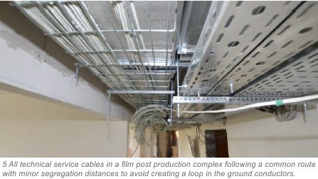
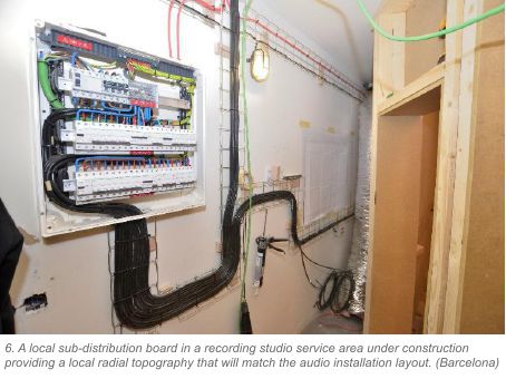 The use of a radial, or star configuration of all system cabling is highly recommended and has shown to be very effective. Care should be taken to avoid circumstances where the adjacent lines of the radial configuration, or ends of the radial spokes, could be inter-connected at any point by either audio, video, or shielded network cables as this could recreate the loop. In the UK “ring main” circuits should be avoided at all costs unless the ring return follows the out cable path, as this is often complex, it is best to just generally not specify a ring circuit for audio. Care should be taken to supply areas likely to be interconnected so they are supplied from a common cable run, tray, or duct. This is especially so when designing studio power and considering performance areas and control rooms. Often installing a sub-distro in the control room or machine room is the most effective solution. On larger entertainment installations consider the options of fitting a local technical sub-distro in the machine (or rack room) which can be fed with an adequate feeder cable and allow subsequent audio and power lines to follow close paths.
Where it is unavoidable in very large systems to run a signal ground path loop around a venue and there simply isn’t an alternative it is best to design a break point into that signal ground loop which cannot get re-patched or mistaken for an electrical fault, otherwise a later operator may need to connect an extra line into something that restores the ground path.
–
Firmly connected together.
Whatever sins we may see at points in the system nothing will cause as much trouble as a poor local ground bonding system. The terms used often in regulations are brilliantly descriptive. Equipotential Bonding. This keeps everything at an equal potential, referenced to ground. Where there is no potential difference we have no ability for a voltage to exist. The lower the impedance of the bonding conductor the greater the strength of the interference current it will resist. Our earth cable is our friend. The stronger the equipotential bonding between our equipment, the less signal can be introduced between devices and the less ground interference can be introduced into our signal paths. A solidly grounded system with effective local equipotential bonding can be immune to all kinds of wiring sins. As much of our equipment will use the protective ground reference as a signal ground reference, either directly or through a decoupling circuit, it will generally be subject to interference from any ground borne signals. This equipotential bond is made by our electrical system, it is imperative that we have a very good low impedance low resistance bond between our items of equipment. We can survive less than ideal system source grounds if our internal equipotential bonding is good. Good equipotential bonding can greatly assist cable screening ability. It is this property that justifies more than anything the use of heavier gauge power cables within the electrical installation, even if our power source is less than ideal.
–
Cable specification.
As we have ascertained that a good low impedance solid electricity supply and ground bond is essential to optimum system performance the principle culprit within our systems is inadequate cabling. Standard electrical requirements are based on constant current loads with occasional peak loads and cable section is calculated for maximum specified operating temperatures and voltage drops. This is inadequate for us in many cases when specifying audio system power supplies. There are many resources available to calculate the effect of a cable upon line impedance and voltage. Suffice to say we should endeavour to maintain as low impedance a supply as possible. When a rack or room is known to contain an item such as a 5,000W power amplifier with a conventional power supply it is best to supply that item individually from as far back down the supply line as possible. In some circumstances this can mean running many power lines to a rack or equipment location.
 Not only is cable section a critical issue but also the interconnects. The best possible situation is one single cable from the power distribution board to one single connector. Where outlet connectors are daisy chained we have potential weak points at each terminal screw. It is imperative to ensure a firm solid connection at these connection points. Where an installation is made with stranded cables the use of bootlace ferrules where the two cables can be tightly compressed within one ferrule is a far better solution before putting the cables under the terminal screws. This way if there is an issue with the terminal screw the issue is not passed on to the remainder of the outlets. It is wise to fully test the source impedance of each individual outlet socket during installation if an increase in value is seen from one outlet to another that is not very small indeed then we probably have an interconnect issue which requires immediate attention.
–
Power line conditioners
 In cases where proper installation has not been possible, where other services are sharing the lines or where there simply isn’t the possibility of demanding a clean source one possible method of resolving issues are various types of power line conditioner. This is often a hit and miss affair, if we are lucky and the issue is minor we may see a reduction in HF noise or distortion artefacts. The reason many filter boxes fail to resolve such issues is simply that they require a solid Neutral and Ground path to filter (short) the interference down to. If the cause of the problem is a poor power line then we are onto a looser from the start as we won’t have this solid path. Many customers see this type of device as a magic bullet cheap fix solution to the more expensive solution of doing it properly or paying a professional to do the job. The majority of well-designed equipment these days already has such filtering inside, so often the use of such devices is futile. One to one high power isolation transformers can be an effective HF filter for downstream HF noise and distortion artefacts, but these need to be employed along with clean solid (legal) local grounding and are expensive to employ on larger systems. Where audio amplifiers are concerned, computer UPS units are to be avoided at all costs, especially ones that permanently re-generate the power line electronically. The load a high power audio amplifier presents is often far too dynamic for the cheap simple inverters used in UPS units and will result in premature failure of the device, or severe current limiting and often voids the warranty. Only large industrial off-grid power inverters with at least a long term (many seconds) 200% peak capacity and are rated for use with high current motor loads (such as elevators) have proven able to reliably deliver the power that audio amplification equipment requires. Any back-up (UPS) system should be hard-bypassed in normal grid operation so as to provide the full low impedance grid supply to the local equipment. The grid should fail to the inverter, the inverter should not be permanently in-line. No inverter can hope to provide as strong a supply as the grid power.
–
Technical grounding
In years gone by when equipment design and EMI rejection was poor it was often automatic to install a dedicated audio technical ground. This however can be as problematic as it is helpful. Often it fails to meet the equipotential bonding requirements of the local electrical regulations, and often it is very difficult to get a very good ground connection from a simple local technical earthing device without resorting to major excavations. In some situations where the supplied utility company system ground can be poor, especially in dryer countries the addition of local supplementary earthing devices can be of assistance, it is recommended that these earthing points are used in addition to the supplied system earth to avoid any potential for multiple separate earths to be at different potentials. It has been observed in densely populated dry cities that two technical earths no more than 15m apart have had adequate potential difference and current to illuminate a single LED when connected between them. This would never be good for an audio system ground. The best policy is to ensure and use a good single system earth for all systems.
There are occasions (TT systems) where single point local grounds are the method of utility company supply, if these grounds are within the required regulation specification they are often quite acceptable audio system grounds, but it can be difficult to get a very good low impedance connection. It is best to check with your utility supplier to see what type of supply earthing system is provided. TN-S TN-C and TN-C-S are all adequate for audio if properly implemented. Additional local grounds are permitted in all instances and are often mandatory when created in the process of bonding of water and gas systems to electrical earth.
–
Testing the lines
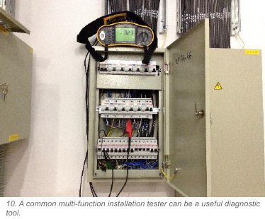 It can be a very good idea for any system installer to make a modest investment in a multi-function installation tester. As much as it is not the job of the audio installer to certify the electrical installation, it cannot be left to the average electrical installer to ensure the lines are to the audio specification. A very poor (for audio) line is easily able to pass an electrical safety test, and so long as the line passes the test the electrical installer sees their job as finished and done. But when we see a pair of identical radial lines from the same board reading different loop impedances we know there is something that is not optimum, even if it does meet the required pass value.
– No electrician will feel motivated to pull their install apart looking for a 0.25Ω difference between two lines that pass by over 1Ω unless they have to, but many a time such variations have shown that minor line faults do exist and when we have such transient loads as we have in audio systems they can be quite serious faults. Purchasing and learning how to correctly use a multi-function installation tester can be a great investment, and such a tester can actually serve well for correct periodic testing of our own audio system install components in lieu of an often inappropriate PAT test. There is a wealth of good educational literature available on the subject of electrical testing that is simple to understand for any competent audio or electronics engineer.
–
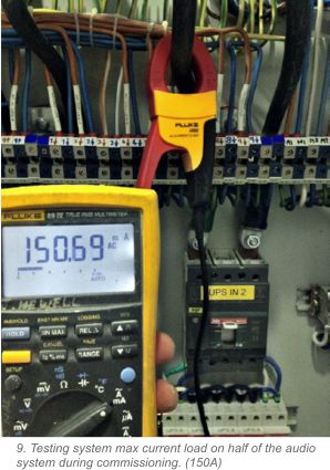
Don’t forget to perform full system load and dynamic power supply readings upon completion of the installation and document all readings for future reference.
–
Talking the talk
 It is crucially important on new build or refurbishment projects to get a good channel of communication worked out between yourself (the audio installer), the project management and the electrical contractors. Groundwork done at the start of the project can make an otherwise uphill battle into an easy ride. It is important that all system criteria be worked out right at the beginning. It can be hard to throw a pile of changes at the other contractors mid-project and often there simply isn’t budget for them. If upon your first contact with the other services they have made an assumption of your needs without proper consultation then it is their negligence, if however you fail to issue your requirements at the start of the project the negligence is yours and getting what you require can then be a very difficult task indeed. If you simply ask for a 32A outlet in the rack area then whatever supply lines you are given at that point is just luck of the draw, it could be fed from whatever is nearest and be on a highly loaded line with all the A/C plant.
–
The payback
 When the job is done and all is working well it can sometimes be hard to see what all the fuss was about, the results of all the hard work are invisible and everything seems to have been for nothing, unfortunately it’s only when things are not done properly that we see the true cost of not doing things correctly. In many cases installers just risk their luck in the hope that everything will be OK, but that just isn’t how a professional should operate. There have been noted cases of engineers returning to AV systems for many months after the delivery date searching for random spurious faults and issues that are a direct result of a poorly implemented power system. With larger audio systems when your power supply reservoirs are struggling to replenish on sagging power lines you can find some of the edge goes from the sound and inconsistencies creep into the results even if noise isn’t a problem. In broadcast and recording studios hours of production time can be regularly lost chasing hums and buzzes and any of us with high quality home systems will know, there is a frightening amount of commercially released recorded material out there with power line noise on the final product. Getting it right is not complicated, just some basic understanding of what makes an acceptable system and good solid low impedance supplies and sensible ground paths will solve the majority of our potential electrical nightmares.
J. Newell, MIOA MinstSCE. Marzo 2017